Synthesis and Synthesizers
Published on 24/05/2022
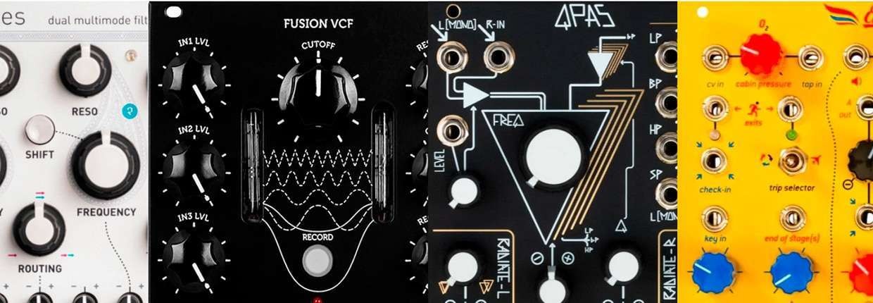
In the previous post we have been talking about Eurorack filters trying to understand which are the features to look for when making a choice. We shall try to understand how to use a Eurorack filter.
Once the device has been selected and assembled in the rack the user has to understand how to include it in the operating architecture of the system and which are the best operating procedures to get to the desired results.
We have a lot of possible alternatives. We will, here, discuss some practical examples to stimulate creatitìvity while remaining consistent with the scope of the discussion.
The classical architecture of a (subtractive) synthesizer starts with one or more oscillators going to a mixer and then into a filter. The filtered signal reaches a VCA before hitting the output.
Thinking about topology, the Eurorack standard allows one to change the position of the modules to get original architectures.
In the following picture, for instance, instead of inserting the filter after the mixer (first diagram) we had put two filters right after the oscillators (second diagram). Each filter is dedicated to a single oscillator and the mixing phase happens after the filtering.
Hybrid configurations are possible (one filter before, one filter after the mixer) simply re-patching the modules.

All these actions are static and give limited results but we have very many possibilities to make things better.
What we do is to use control signals to change (a lot, sometimes) the cards on the table.
Control signals derive from keyboards, sequencers, LFO and Envelope Generator.
The keyboard signal is used to allow the Pitch tracking. This connection makes the filter cutoff frequency to follow the pitch in order to have a homogeneous behavior through the pitch extension of the instrument.
CoBy using the sequencer other uses can be imagined sending to the filter patterns with different step from the melody. This will allow it to activate specific features depending on the specific input where the sequencer gets connected.
Cyclic variations are usually obtained with LFOs.
The envelope generator is used when the filter effect is meant to be bound to the evolution of the single note pressed on the keyboard. Changing the cutoff frequency or the resonance (or both) based on the plaid note (and its gate signal) increases expressiveness.
The same signals can be used to vary the filter topology if allowed by the specific hardware.
Let’s continue to consider the Mutable Instruments FIlter that we have already discussed in the previous post.

The module contains two filters with following possible controls:
These parameters can either be controlled manually or remotely.
With two filters it is possible to implement the above mentioned configurations connecting the filters either after the oscillators or after the mixer (these options give us a greater control over the filter topology).
With the two filters connected in series or in parallel we can realize time varying two band equalizers.
The variation can be cyclic via LFO, linked to the single notes via an envelope generator or dynamically driven by a sequencer.
The sequences can eventually be random if we use a noise generator followed by a Sample&Hold.
The same criteria can be applied to the filter topology obtaining a morphing of the filtering mode (continuous moving from low pass, band pass and high pass filtering).
Influencing cutoff frequency and resonance at the same time further possibilities are given to influence tone and expressivity.
Needless to say that the harmonic content can be controlled via the Drive input.
The pitch tracking is managed via the V/Oct input. This one does not have a dedicated attenuator so an external one could be suitable to manage the pitch tracking with percentages lower than 100%. The possibilities can be even more if we include sophisticated control signal generators in the system such as the versatile Make Noise Maths.
Let’s go, at the end, a little bit in greater detail about the actual connections to realize the described topologies using the Mutable Instruments Blades.

The first picture explains how to connect the Blades after the mixer.

In the second picture the two filters are connected to each oscillator and then to the mixer.
In this way we lose the possibility of the double dynamic filter but we gain the chance to filter every single oscillator sound.
None of the configurations is better by definition. The choice really depends on the results that the producer wants to reach.
In this post we have been looking at how to use the enormous filter potential in modifying audio signals.
We have then managed to apply the previously understood concepts to a case study.
The huge amount of possibilities offered by the Eurorack marker doesn’t allow us to explore all the practical possibilities, we have been working on a single case to illustrate how to proceed in the real world.
Let’s meet in the next posts for further investigations about the modular synthesis world. See you soon!
Join us today and get 5% off your next order!

Empty cart